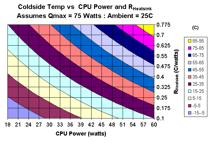
Let us now look at the relationships of RHeatsink , QCPU and Qmax in a more general sense. Below, you see a few contour plots. The first thing to consider is: Given a powerful TEC ( Qmax = 75 watts), what kind of CPU temperatures can be expected based upon varying heat load (QCPU) and varying RHeatsink? The following two plots are based upon performance for the TEC at 12V.

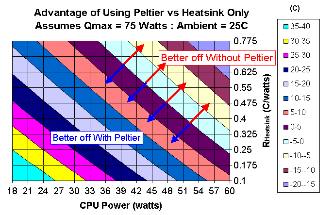
This plot shows cold side temp of the TEC for various heat loads and heatsink capabilities. So for example we can see that at QCPU= 33 and RHeatsink = 0.475, the cold side temp is about 28C, or 3C over ambient - not too bad. What about the fact that the TEC is adding heat? We must make sure that we are progressing not regressing! For that I took the same information and compared it to the temperature that would have been achieved at the same CPU load and with the same heatsink but without the TEC. I subtracted the calculated temperature with TEC from the calculated temperature without TEC. Thus, in the next plot, I am showing the advantage of using the TEC. When the numbers are positive, the TEC does improve cooling; when they are negative, the TEC is a disadvantage.

Again, what is plotted here is the advantage of using the TEC versus not using one - for example from the conditions before (QCPU= 33 and RHeatsink = 0.475) we see that the advantage is about 12.5°C. The TEC coldside temp was 28°C; using the heatsink alone, we would have reached a temperature difference of 33 watts * 0.475°C/W = 15.7°C. Add that to 25°C = 40.7°C, which is 12.5°C hotter than the solution with the TEC. I think this kind of plot can be really interesting - it shows us how quickly it can go bad if we use either an undersized TEC or an undersized heatsink.
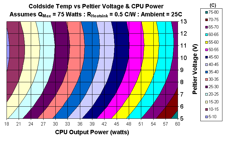
How about TEC voltage? Again plotted against CPU power, same TEC ( QMax = 75 watts) but choosing RHeatsink = 0.5 C/W.

This is quite interesting because it shows two things: First of all there is an optimum voltage - in this case about 10.5 - 11.5 volts, depending upon the power. Second, it shows that you can get away with a much lower voltage and still do some serious cooling. This may be important in the case that your power supply is putting out less than 12 volts due to the extra load of the TEC. Of course, under these circumstances one should consider an alternate power source for the TEC.
The last thing I'd like to show is a plot
that illustrates how big the TEC and heatsink should be, based upon the power
load.
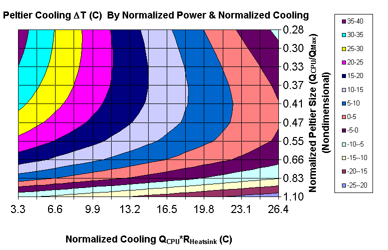
I've normalized the CPU power on the TEC Qmax as thus:
Normalized Power = QCPU/Qmax.
I also normalized
the CPU power on RHeatsink:
Normalized Cooling = QCPU*RHeatsink.
The purpose of this is that the plot directly tells how big the TEC
and heatsink should be based upon the power requirement. The temperature
shown is the advantage over using the same heatsink without the TEC.

Coincidentally, the values along the horizontal axis also happen to be the temperature rise over ambient that the heatsink working alone (without TEC) would produce.
The temperature contours are again the advantage of using the TEC versus using the same load and heatsink without the TEC. Thus at 0 is is break even - positive numbers (C) indicate that the TEC is helpful, negative numbers indicate that the TEC is heating the CPU. So we can immediately see that if the heatsink alone can not keep the CPU less than 26°C over ambient - then under no circumstances will it ever get better when you add a TEC. Furthermore, you should add a 5-10°C penalty for the fact that the extra heat inside your case caused by the TEC will work to your disadvantage - thus I'd say that you really need a heatsink (or watercooler) that will keep your CPU no more than 15C -18C above ambient for it to be suitable for applying a Peltier. Now - bear in mind that this is the CPU temp measured at the interface with the heatsink - if you are measuring the temperature of the CPU from the CPU's internal temperature diode, then you may see a higher temperatures than at the heatsink interface.
If the CPU load is about equal or greater than the TEC QMax - then even the very best heatsink in the world will not justify using the TEC.
Finally, we can see that the optimum size of the TEC is such that the CPU power is 1/3 - 1/2 of QMax. If you have a really good cooler, such as a powerful water cooler, then get a TEC that has QMax = 3 times the CPU heatload. If the heatsink is marginal (15C-18C above ambient without TEC) then go for QMax = 2 times the CPU heat load.
As mentioned before, you can download an excel spreadsheet with the the functions I used to create the above plots. As with any computation tool - check to see if the results make sense. Remember that your outputs are only as good as your inputs (garbage in = garbage out). All theory comes from Melcor. Basically there are two user defined functions that may be useful for someone engineering their own peltier cooled assembly. One function (peltier) will calculate the heat transferred across the TEC - this is really only a support function for (cputemp) which will calculate the coldside temp directly. The functions require that you know how many thermocouples are in your TEC and you must also come up with something known as the "Geometry factor". As I mentioned above I found from the Melcor data that G = Imax/50 - but the acid test is to recreate a manufacturer's supplied curve at the specified temperature.
After you open up the spreadsheet there is a page sort of akin to a user's manual - and another page to chart the TEC performance. You can access these two functions by inserting a user defined function. I did not protect the VBA stuff so feel free to hack it - but this is my material - please give credit where it is due.
Whether condensation occurs, depends on the temperature of the cooled object, on the ambient
temperature, and on the air humidity. Here is a table that will give you an indication
whether you are risking condensation problems:
|
Air temperature |
|
|
|
|
|
|
|
|
|
|
|
|
|
|
|
|
|
|
|
|
|
|
|
|
|
|
|
|
|
|
|
|
|
|
|
|
|
|
|
|
|
|
|
|
|
|
|
|
|
|
|
|
|
|
|
|
|
|
|
|
|
|
|
|
|
|
|
|
|
|
|
|
|
|
|
|
|
|
|
|
|
|
|
|
|
|
|
|
|
|
|
|
|
|
|
|
|
|
|
|
|
|
|
|
|
|
|
|
|
|
|
|
|
|
|
|
|
|
|
|
|
|
|
|
|
|
|
|
|
|
|
|
|
|
|
|
|
|
|
|
|
|
|
|
|
|
|
|
|
|
|
|
|
|
|
|
|
|
|
|
|
|
|
|
|
|
|
|
|
|
|
|
|
|
|
|
|
|
|
|
|
|
|
|
|
|
|
|
|
|
|
|
|
|
|
|
|
|
|
|
|
|
|
|
|
|
|
|
|
|
|
|
|
|
|
|
|
|
|
|
|
|
|
|
|
|
|
|
|
|
|
|
|
|
|
|
|
|
|
|
|
|
|
|
|
|
|
|
|
|
|
|
|
|
|
|
|
|
|
|
|
|
|
|
|
|
|
|
|
|
|
|
|
|
|
|
|
|
|
|
|
|
|
|
|
|
|
|
|
|
|
|
|
|
|
|
|
|
|
|
|
|
|
|
|
|
|
|
|
|
|
|
|
|
|
|
|
|
|
|
|
|
|
|
|
|
|
|
|
|
|
|
|
|
|
|
|
|
|
|
|
|
|
|
|
|
|
|
|
|
Condensation problems can be avoided by properly insulating the cooled components. The better solution is to use a temperature control for your TEC, to avoid temperatures that are so low that condensation becomes a problem. A simple circuitry, like the one presented here on The Heatsink Guide is useful for controlling fan speed, but not for controlling peltier elements, due to their high power usage. Pulse-width modulation can be used for controlling peltier power; this is a rather complex issue, and beyond the scope of this guide.
In conclusion, TECs are solid state heat pumping devices that can reduce component
(CPU) temperatures, but they require some forethought to apply. If the TEC is misapplied, then the
unit may actually heat your CPU rather than cool it. The most important
thing is that the heatsink and the TEC must be properly sized to suit the
heat load. The heatsink must be at least good enough that it will keep the
CPU only 15-18C above ambient without the TEC. The TEC must have a maximum
heat transfer capability about 2 - 3 times more than the amount of heat
that the CPU puts out.
Note: This article was originally written by "Bo", a visitor of The Heatsink Guide,
who wishes to remain anonymous, and only slightly modified by me.
Thank you Bo for sharing this article with us!
All pages copyright © 1997-2010 Tillmann Steinbrecher
Legal information / Disclaimer / Impressum