THE HEATSINK GUIDE: Peltier Guide, part 2
Getting into the details
The second part of the Peltier Guide deals specifically with sizing peltiers and heatsinks,
to fit a given application. Hopefully it will also show some of the problems in more detail,
and help you judge about merits and tradeoffs when using peltiers.
The fact that you are still reading, and weren't scared off by the first part, shows that you have
a keen interest in peltier cooling. If you are more interested in general information
about Peltier elements, or in in-depth information about the theory behind them, you should
definitely have a look at Melcor's excellent Thermoelectric
Engineering Handbook.
This article here mainly focuses on how to apply peltier cooling to PC processors or graphics chips;
it is not as general as the information you can find on the websites of Peltier manufacturers.
First, a word of warning: Read the disclaimer before proceeding. If
you damage something while following the instructions here, I cannot be held responsible. Do
not supply power to a peltier element without a heatsink, after a while it will overheat
and the connectors will melt.
In the last part of the guide, you will find an Excel spreadsheet with VBA code that will
help you with the necessary calculations for designing a peltier-based cooling system for your PC, but I ask
you to please read the article first before you download the spreadsheet.
Peltier Performance
 One
thing we must consider is that a thermocouple will always be a thermocouple
- and thus when you apply a voltage and get a temperature difference -
you will also cause a back voltage created by the Seebeck effect. This
is very similar to the back EMF created within an electric motor - and
thus much like motors TECs show a negative linear load dependent output
curve. The other thing that happens when a voltage is applied across the
TEC unit is that current flows through the TEC. This causes internal heating
through I2R losses. This is a very important fact because this
imposes a lot more heat on the heatsink to cool - we will get to that later.
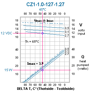
A performance curve from Tellurex
is shown here at the left. This, by the way, is the same curve that Joe
over at overclockers.com
shows in one of his articles.
The curve shows heat pumped versus temperature
difference achieved across the peltier for 3 different current inputs.
I find this plot not particularly easy to read. The main problem I have
is that the information is presented at constant current, whereas PC freaks
are likely to have a constant voltage source available. The other thing
that is not shown is the power generation from the TEC itself - you can
however glean this information from the voltage and current. I have rearranged
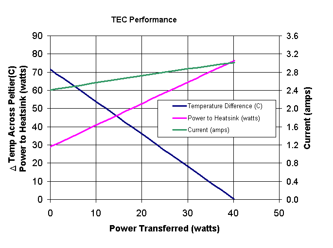
the same information into another chart I find more usable.

This chart shows the same TEC as above
- but only at 12 volts. The left-hand vertical axis is for both temperature
difference (C) and also for total power to heatsink (watts). The right-hand
vertical axis is for current(amps). The first thing you'll notice is that
the independent axis is power transferred (CPU power). The next thing you
might notice about this format is that you can immediately see the amount
of power transferred to the heatsink as a function of the amount of power
transmitted by the TEC. For example at 15 watts of heat transfer across
the peltier element another almost 30 watts of heat is added by I2R
losses to make nearly 45 watts transferred to the heatsink. This illustrates
that TEC applications add a lot of "overhead" heat to the total system, as
it was already pointed out in the first part of this guide.
Note: This article was originally written by "Bo", a visitor of The Heatsink Guide,
who wishes to remain anonymous, and only slightly modified by me.
Thank you Bo for sharing this article with us!
All pages copyright © 1997-2010 Tillmann Steinbrecher
Legal information / Disclaimer / Impressum
 One
thing we must consider is that a thermocouple will always be a thermocouple
- and thus when you apply a voltage and get a temperature difference -
you will also cause a back voltage created by the Seebeck effect. This
is very similar to the back EMF created within an electric motor - and
thus much like motors TECs show a negative linear load dependent output
curve. The other thing that happens when a voltage is applied across the
TEC unit is that current flows through the TEC. This causes internal heating
through I2R losses. This is a very important fact because this
imposes a lot more heat on the heatsink to cool - we will get to that later.
